6 minutes
UniFi WiFi Multi-SSID & Roaming with Cisco PoE+ Switches & Self-Hosted Controller

Setting the stage
Many people pick up their new UniFi access points for their home, starry-eyed with dreams of roaming and multiple SSIDs, allowing fast and segregated WiFi for all their needs.
Then reality sets in. You go to plug in your access points and realize you’ve got no ports left on your ISP router. Fine, go on Amazon and purchase your $20 8-port switch.
Okay, now it’s time to rock and roll. You plug it into the Amazon switch; aaaaaand nothing happens. You’ve forgotten to buy some PoE injectors. They’re just as dead as they were in the box.
“Alright, surely this is the last thing,” you say as you place yet another order on Amazon to facilitate your wireless ambitions. The next day, your injectors arrive, you plug them in, download the UniFi app, and what’s this? Something about a Cloud Key? At this point, you’re about to use them for the sport they were shaped for, throwing them for the dogs to fetch.

Alright, hit up Marketplace and buy yourself a Cisco PoE-enabled enterprise switch. Now call your grandson over and kickstart his IT career by saying, “No Roblox till the WiFi is working.”
But boss, why a Cisco switch?
They’re cheap and readily found on the secondhand market. Your wallet has suffered enough buying prosumer APs to begin with. The heartburn associated with setting them up will benefit you in the long run, I promise. Even if you decide on something else, you’ll gain a deep understanding of how it’s done by reading the Cisco CLI commands.
What you’ll need
- Computer
- Docker
- UniFi APs
- Cisco PoE-enabled switch
- VLAN-capable router
- Internet (Duh)
Defining some things
VLANs
Envision a dumb switch: you plug something into it, and everything connected to it can talk to everything else. Now imagine a second one, it is separate, and switch A devices cannot talk to switch B devices.
That is VLANs in a nutshell, but done inside the switch itself.
Cisco Stuff [LLDP, Power Inline, IOS]
- IOS [XE]
- Classic Cisco operating system
- Runs directly on the hardware
- Custom-made for the hardware
- XE version runs on top of Linux
- Switchport
- A spot you plug into the switch is a switchport
- You can configure the switchport to behave differently
- Access/Trunk mode
- Access: You’re directly connected to a specific VLAN; no tagging needed
- Trunk: You can tag your traffic with multiple VLANs, allowing one port to carry multiple networks
- Trunk Native VLAN: A trunk needs a default VLAN even if you don’t tag traffic yourself. This is the Native VLAN.
- LLDP (Link Layer Discovery Protocol)
- Handles capabilities of different network devices
- The AP will tell the switch how much power it needs; otherwise, it gets a default 15 watts, which may not be enough
- Enable/Configure Terminal
- Enable: Access slightly more privileged information
- Configure Mode: Configure the switch completely
AP
“Access Point” is often confused with your ISP router and may be known as:
- WiFi thingy
- Router
- Internet hub
- “The Internet”
- ${ISP_NAME}
It’s the device that handles the wireless network.
WiFi Stuff [2.4GHz, 5GHz, 6GHz]
Key points:
- Higher frequency = faster but shorter range
- Lower frequency = slower but longer range
- Older or cheaper devices sometimes only support 2.4GHz (IoT devices especially)
Topology
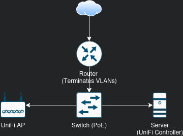
This is the bare minimum physical topology needed for the proposed WiFi plan.
In the logical topology, we will use a minimum of 3 VLANs:
- MGMT
- WiFi
- Guest
This may vary based on your needs; the intent of the tutorial is to show you how to do it.
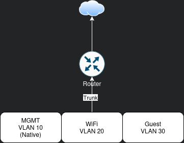
The router handles routing between VLANs and to the Internet. More advanced in-switch routing exists but is out of scope.
The Switch
We’ll use a Cisco 3850. On Marketplace, you can find one for $60–$1000 depending on the model and features.
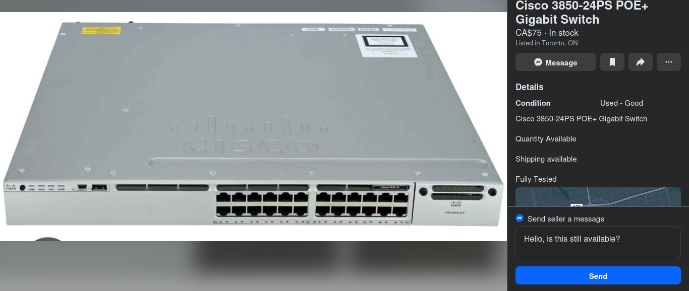
For our purposes, we need:
- Gigabit ports
- PoE support
People spend more on a single RAM stick nowadays, save that money and buy an enterprise switch to play with.
Note the mini-USB port on the front: this is how you communicate with it without a USB-to-serial cable. The full-size USB port is typically used for copying files (firmware updates or logs).
Plugging Things In
We’ll assign ports as follows:
- Router = interface GigabitEthernet1/0/1
- AP = interface GigabitEthernet1/0/2
- Server = interface GigabitEthernet1/0/3
Accessing The Switch
- Plug in a mini-USB cable to the switch.
- Download PuTTY, a cross-platform client for accessing serial consoles.
- Choose Serial as the connection type and input the USB serial device, usually
/dev/ttyUSB0on Linux. - Connect.
- Hit Enter. You’ll see the setup wizard (if the switch was wiped). You can complete or skip it. I tend to skip.
Factory reset instructions:
https://www.cisco.com/c/en/us/support/docs/lan-switching/vlan/217969-reset-catalyst-switches-to-factory-defau.html
Enable LLDP
enable
configure terminal
lldp run
exit
write
This allows the AP to communicate its power requirements.
VLANs
enable
configure terminal
vlan 10
 name MGMT
 exit
vlan 20
 name WiFi
 exit
vlan 30
 name Guest
 exit
exit
write
Configure Switchports
enable
configure terminal
interface GigabitEthernet1/0/1
 description Trunk to Router
 switchport trunk native vlan 10
 switchport mode trunk
 spanning-tree portfast
 exit
interface GigabitEthernet1/0/2
 description PoE WiFi APs
 switchport trunk native vlan 10
 switchport mode trunk
 spanning-tree portfast
 exit
interface GigabitEthernet1/0/3
 description Server
 switchport mode access
 switchport access vlan 10
 spanning-tree portfast
 exit
exit
write
interface GigabitEthernet1/0/3: Choose which interface to configuredescription Server: Add a note for clarityswitchport mode access: No VLAN taggingswitchport access vlan 20: Assign to VLAN 20spanning-tree portfast: Prevent delays when connecting devicesexit: Exit interface config modewrite: Save your configuration
Observe VLANs
show vlan
Check that your VLANs are active.
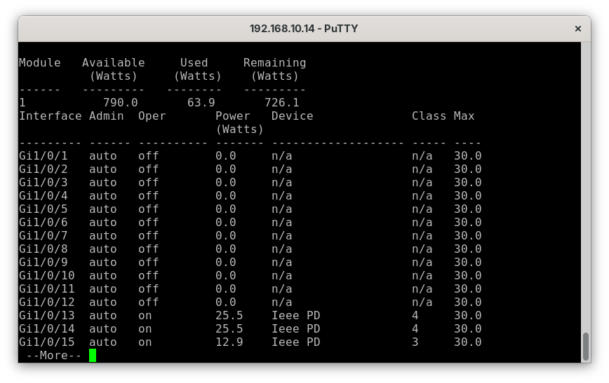
Observe PoE Statistics
show power inline
This shows which ports are PoE-enabled and the power usage.
The Router
Follow this guide to configure VLANs on OPNsense:
https://www.zenarmor.com/docs/network-security-tutorials/how-to-configure-vlan-on-opnsense
Firewall rules example:
- MGMT <-> Internet = Blocked
- WiFi <-> Internet = Allowed
- Guest <-> Internet = Allowed
- MGMT -> WiFi = Allowed
- MGMT <- WiFi = Blocked
- WiFi <-> Guest = Blocked
- Guest <-> MGMT = Blocked
- Guest <-> WiFi = Blocked
The Server
Assuming Linux. We’ll use Docker Compose.
Installing Docker
curl https://get.docker.com | bash
Verify and review scripts from the Internet before running.
Deploying the Cloud Controller
Get the latest Docker Compose file from:
https://hub.docker.com/r/linuxserver/unifi-controller
Edit volume paths as needed.
---
version: "2.1"
services:
  unifi-controller:
    image: lscr.io/linuxserver/unifi-controller:latest
    container_name: unifi-controller
    environment:
      - PUID=1000
      - PGID=1000
      - TZ=Etc/UTC
      - MEM_LIMIT=1024 # optional
      - MEM_STARTUP=1024 # optional
    volumes:
      - ./unificonfig:/config # CHANGE ME
    ports:
      - 8443:8443
      - 3478:3478/udp
      - 10001:10001/udp
      - 8080:8080
      - 1900:1900/udp # optional
      - 8843:8843 # optional
      - 8880:8880 # optional
      - 6789:6789 # optional
      - 5514:5514/udp # optional
    restart: unless-stopped
  unifi-db:
    image: mongo:6.0.19
    environment:
      - MONGO_INITDB_ROOT_USERNAME=root
      - MONGO_INITDB_ROOT_PASSWORD=mongopass # changeme
      - MONGO_USER=unifi
      - MONGO_PASS=mongopass # changeme
      - MONGO_DBNAME=unifi
      - MONGO_AUTHSOURCE=admin
    volumes:
      - ./mongo:/data/db
      - ./mongoscript/init-mongo.sh:/docker-entrypoint-initdb.d/init-mongo.sh:ro
    restart: unless-stopped
Use the init-mongo.sh file from:
https://docs.linuxserver.io/images/docker-unifi-network-application/#setting-up-your-external-database
Boot the container:
docker compose up -d
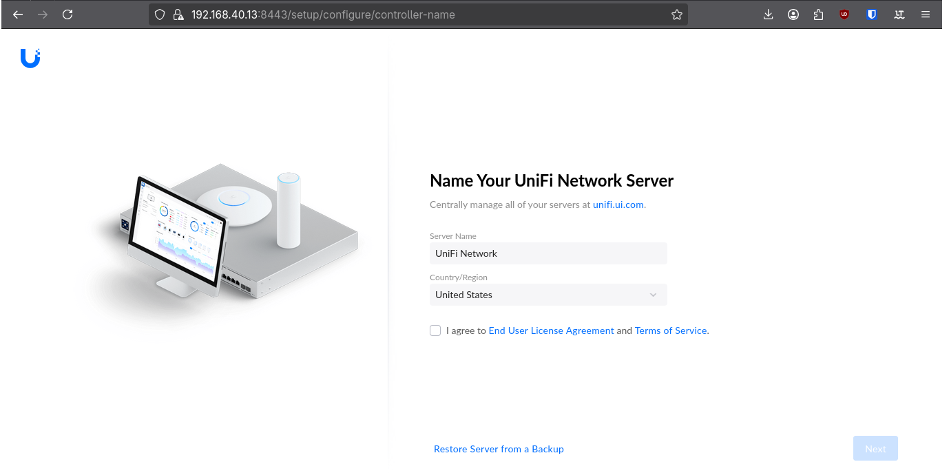
Access the controller at https://<SERVER_IP>:8443. Setup your account and adopt your APs.
Adopting the AP
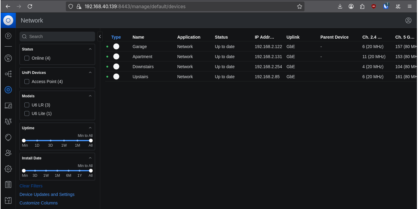
Click Adopt for each AP. Updates may occur before adoption completes.
In case you need to adopt by alternative means, see the link below.
SSH adoption guide:
https://blog.ktz.me/how-to-adopt-a-unifi-ap-with-a-remote-controller/
Creating a Network
Settings > Networks > New Virtual Network
- Name: WiFi
- VLAN ID: 20
Repeat for Guest:
- Name: Guest
- VLAN ID: 30
Creating an SSID
Settings > WiFi > Create New
- Name: YourWifiNetwork
- Password: Password1234
- Network: WiFi
Repeat for Guest.
Your APs should now broadcast your new WiFi networks.
Roaming
Roaming functionality is enabled by default when multiple APs are adopted and broadcast the same SSIDs.
homelab unifi networking cisco vlans wifi
1239 Words
2026-01-20 00:00 (Last updated: 2026-05-02 05:26)
2f80c01 @ 2026-05-02