6 minutes
Lab Writeup Series: 2025 Update
It’s been a while. New lab, new me.
A lot has changed, but I’m still at it. The lab keeps growing.
In fits and starts, I stumble forward toward something resembling a home datacenter.
To those who have read my previous posts about my lab, just know that it’s a work in progress, and there’s always something new going on. This iteration is much prettier than the previous one.
Intro
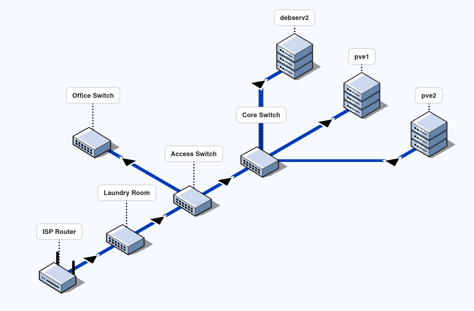
Above is a simplified view of the physical network topology for my home. The bulk of the networking happens across these devices. This is a family household of roughly 10 ± 2 people, most of whom are heavy users of internet-connected devices. One other person and I work from home and rely on a rock-solid internet connection for Zoom.
It may not look like much, but the real magic lies in the abstractions.
Physical Topology
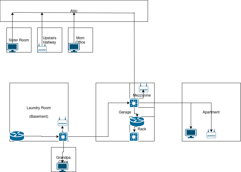
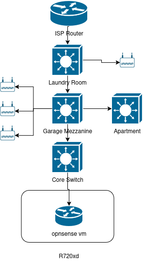
See above the detailed physical topology of the network as placed throughout the house. Now observe the abstracted topology below. This should present a clear path by which data flows throughout the phycical network infrastructure.
The core switch is set up to handle all east-west traffic within the network. The rest of the switches act primarily as access switches with trunks and access ports configured for varying purposes.
The bulk of the access traffic is handled via the mezzanine switch. This switch takes all traffic coming from the bulk of the wifi access points, wired appliances, and trunks to and from the rack.
Hardware
This is where the fun begins. The physical makeup of the network was always a fascination for me. Beyond configuring network devices on GNS3 or some other platform, I always loved plugging things in, and seeing the activity lights blink. The faster the blink, the better.
The switches strewn throughout the house are the Cisco 3850 switches with PoE. My 3750, now retired; it earns it’s rent as a management switch. The only other instance of other network hardware types is in my office (Apartment). My office has a 3560-cx. Previously a full size 3850. This setup was loud and hot; now silent and cool.
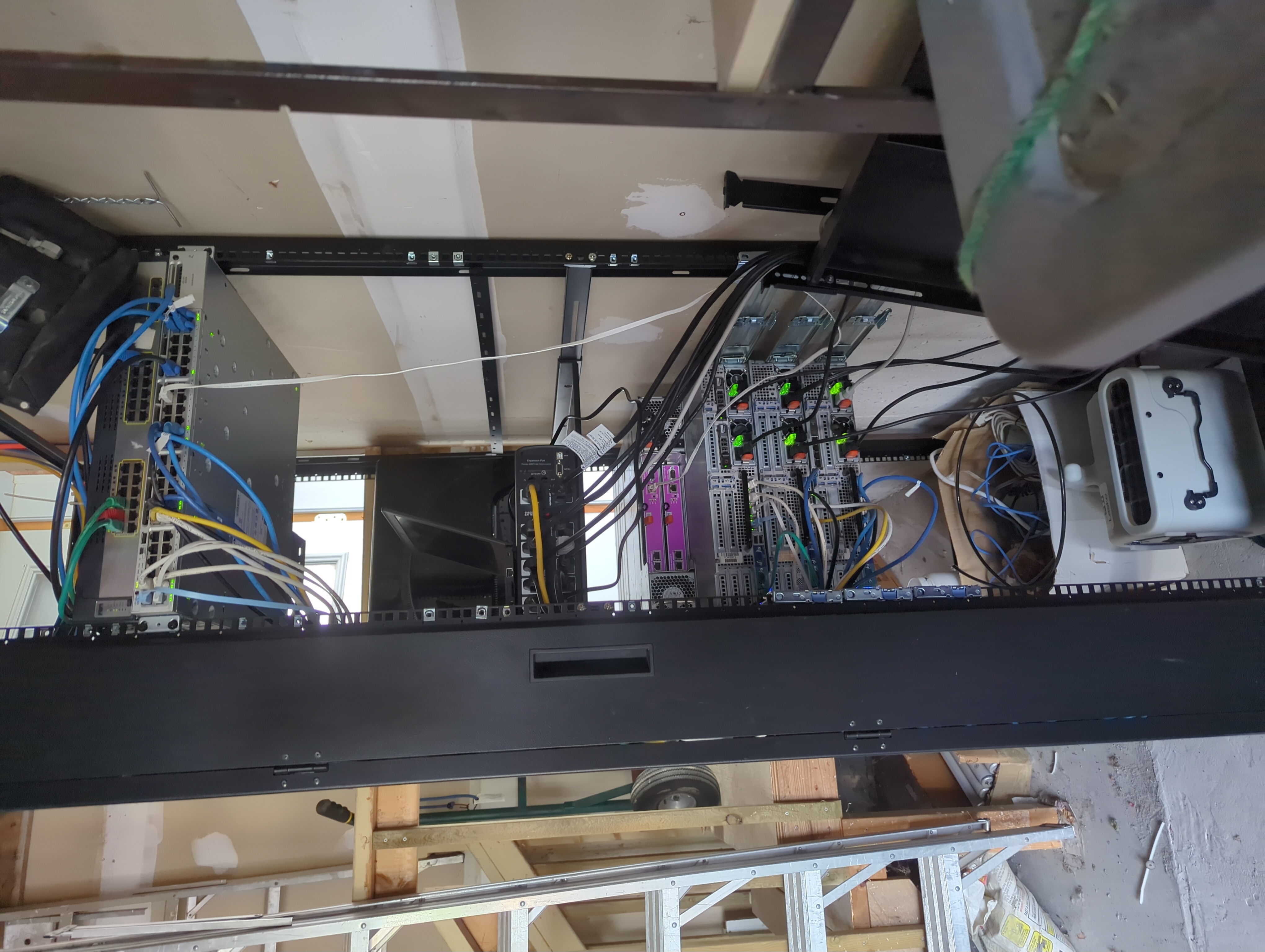
Above is how my garage keeps warm in the winter. Being a Canadian, one has to deal with freezing weather from time to time. Per the statistics provided to me from zabbix, this setup is enough to keep the entire garage above freezing well below -20 degrees Celcius outside. It is only when the garage door is open for an extended period that I start getting thermal alerts.
Perplexingly; the SAN seems to belt out far more heat than the rest of devices. This is despite the fact my usage is quite low for this device. This holds true for the SAN devices at my work place as well. I can stand behind a 16 unit blade server at full utilization and not feel it. The rack of SANs however, it is quite toasty.
You may refer to my previous descriptions of the server hardware in previous posts. That’s about where the similarity ends.
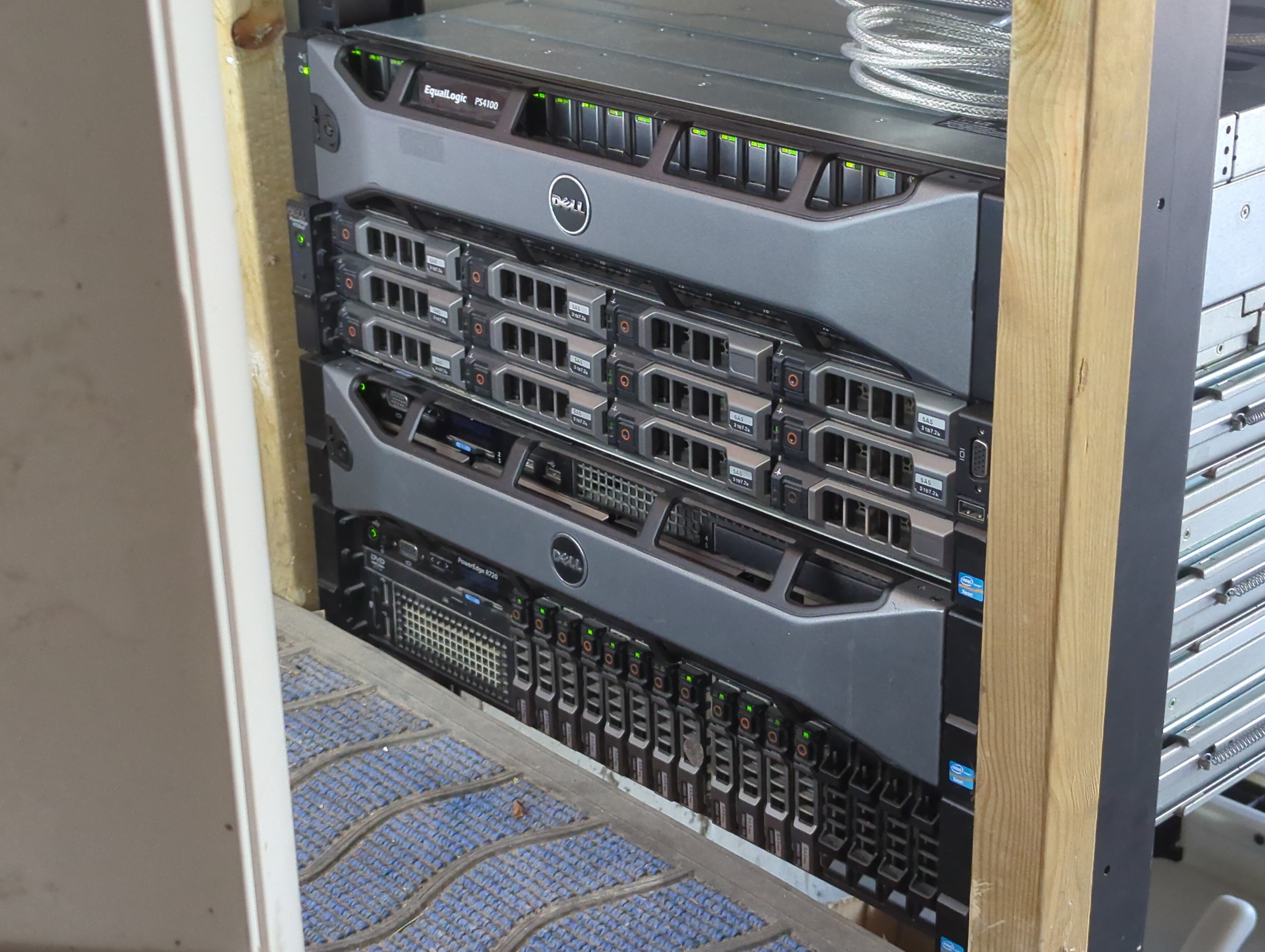
Ordered from top to bottom; The following are the devices as seen in the picture above.
- Equallogic PS4100 SAN
- Dell R720xd Debian (debserv2)
- Dell R720 Proxmox node (pve1)
- Dell R720 Proxmox node (pve2)
I intend to convert my remaining server to proxmox, but this will require further decoupling. Currently, debserv2 contains my opnsense vm which takes up 2 physical interfaces on the device. This along with several other storage intensive self-hosted applications makes the conversion a tad cumbersome. This adventure will be documented in further posts.
Links between the core switch and the mezzanine switch is a 2 interface port channel. The physical location of the mezzanine switch in relation to the rack is overhead on a wooden storage structure lovingly referred to as the mezzanine.
All servers are connected to the core switch with LACP 2-4 link bonds. All trunked to the relevant vlans. The SAN lives on it’s own 2 VLANs. To enable multipathing, of course.
Management links all go to the management switch above the core switch. This not only saves space, but allows me to administer all relevant devices even if the core switch is down. All it requires is my physical presense. Worst case scenario, I would use a serial cable.
WiFi access points are Unifi 6 Long Range access points. Adminstered via a selfhosted cloud-key. Powered via the 3850 PoE switches. I had considered other more technical wifi solutions, but I would also have to administer them when I’m gone. For that reason I went the prosumer route. They have a nice UI and graphs, people love their pretty graphs.
#TODO
- 10G trunk via addon for 3850 switches
- OSPF port channel links between all switches (Equal cost multi path)
Logical Topology
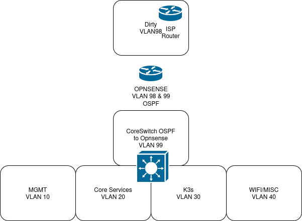
Excluding the storage appliance, the image above represents the homelab network as it exists now. 5 major VLANs.
North-South routing handled via OPNSense VM. Coreswitch exchanges routing information with OPNSense via ospf.
I’ve largely left my extended family to their own devices with their network. Their devices live on VLAN 98. As far as they’re concerned, they would not be able to tell that I’m running a parallel infrastructure.
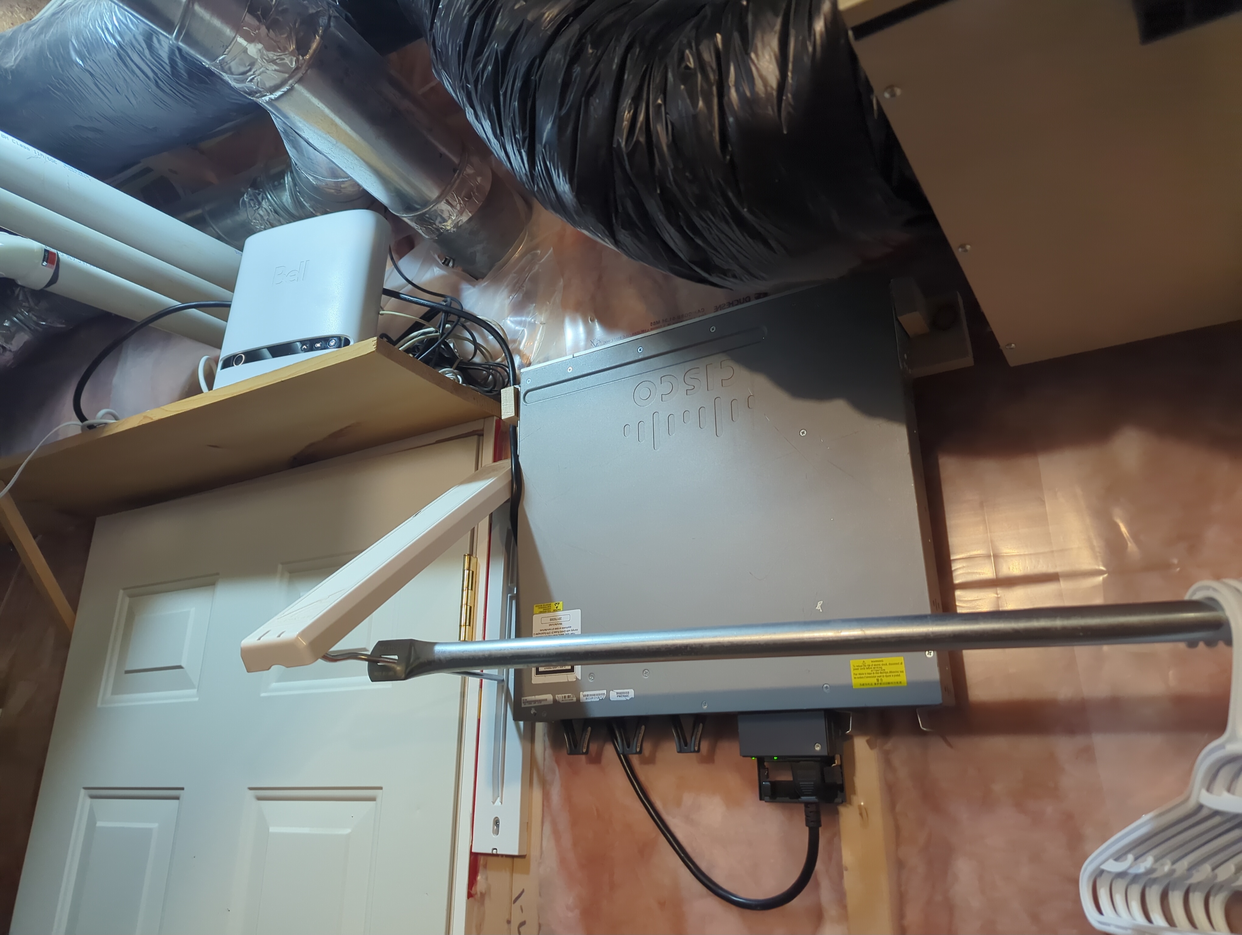
Bell Fibe routers have a feature called Advanced DMZ. While I’d love to bypass the device altogether, that would interrupt phone and TV services.
The laundry room switch is configured to accept all traffic from the ISP router on a port set to access VLAN 98. VLAN 98 is trunked all the way to the core switch, accessed via the OPNSense VM. OPNSense VM is set to be in the Advanced DMZ, thus exposed to the internet. The rest of my network exists south of the OPNSense VM.
MGMT
VLAN 10 handles all management traffic. This includes iDrac, SAN mgmt address, Proxmox UI, and certain other services that would monitor them.
Core Services
Core services like DHCP, DNS, password manager, and more, are hosted on VLAN 20.
k3s
Services not considered to be core services are largely hosted on my k3s cluster. More on this in another post.
WiFi/Misc
Unifi WiFi access points are trunked to access multiple VLANs. One for my extended family, and one for me.
WiFi
2 SSIDs are configured to broadcast from all access points. One trunks to vlan 98, my extended family’s wifi. One for myself, on VLAN 40.
Roaming is enabled, as this structure is large enough to require multiple APs. Reference the physical topology diagram near the top for a representation of their locations.
homelab hardware hypervisor server networking cisco proxmox
1085 Words
2025-12-22 00:00 (Last updated: 2026-05-02 05:26)
2f80c01 @ 2026-05-02